Choosing a 5th Axis Cnc Machine is a serious production decision, not a simple equipment purchase. The right model can reduce setups, improve tool access, and hold tighter accuracy on complex parts. The wrong model may create expensive downtime, difficult programming, and unused capability.
Peter Zelinski, editor-in-chief of Modern Machine Shop and a respected manufacturing technology authority, has said, “The best machine is the one that fits the work.” That principle deserves attention. A machine with impressive specifications may still fail your daily requirements. Your parts, materials, tolerances, operators, and floor space should guide the decision.
This guide examines seven practical factors before you commit. They include machine rigidity, working envelope, rotary-axis design, spindle performance, control software, service support, and total ownership cost. A titanium impeller demands different stability than an aluminum bracket. A small aerospace supplier also faces different risks than a high-volume automotive plant.
Look closely at real evidence. Request sample cuts, inspect test-part surfaces, and ask how accuracy changes after long production cycles. Speak with current users, not only sales representatives. Their experience often reveals details hidden in brochures, such as awkward access to filters or slow probing routines.
There is no perfect machine.
Even experienced buyers can misjudge future workloads. You may also overestimate your team’s programming readiness. Honest planning, careful comparisons, and practical testing will help you choose a 5th Axis Cnc Machine that supports reliable production rather than merely occupying valuable floor space.
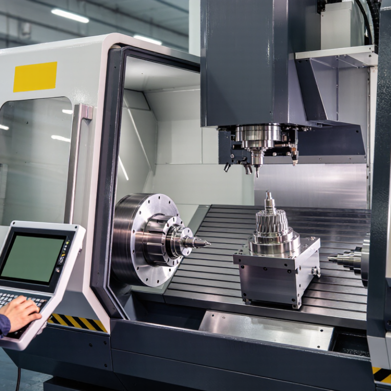
Start with the part, not the machine brochure. A 3+2 process tilts the tool, locks the rotary axes, and cuts from a fixed angle. It suits prismatic parts, drilled patterns, and shallow cavities. Fewer setups can improve accuracy and reduce handling time. However, it may leave witness lines between indexed positions.
Full 5-axis simultaneous cutting moves three linear and two rotary axes together. It is valuable for turbine blades, impellers, medical surfaces, and deep sculptured molds. The tool can maintain a better angle against the surface. This often supports shorter tools and smoother finishes. A 2024 Grand View Research report estimated the global CNC machine market at more than 80 billion dollars. That growth reflects rising demand for complex, automated production, not proof that every job needs simultaneous motion.
The real test is cycle time, tolerance, and programming effort. A 2023 Deloitte manufacturing survey found that many manufacturers still struggle to scale advanced digital capabilities. That warning matters. Full 5-axis cutting demands stronger post-processors, simulation, probing, and operator training. I have seen a simple 3+2 strategy beat simultaneous cutting on stable repeat jobs. My own rule is imperfect. Run both strategies on one representative part. Compare setup minutes, tool life, surface deviation, and inspection results. If simultaneous motion saves only a few minutes, its extra complexity may not earn its keep.
7 Tips for Choosing a 5th Axis CNC Machine
Size, Travel, Table Load, and Spindle Power from MRR Data
Global machine-tool consumption reached roughly $85 billion in 2023, according to the 2024 World Machine Tool Survey. That investment makes sizing decisions less forgiving. Tip 1: measure your largest finished part, not its raw blank. Add fixture clearance, tool reach, and rotary-axis sweep. Tip 2: check usable X, Y, and Z travel after installing the 5th-axis unit. A compact table can quietly remove valuable Z clearance.
Tip 3: calculate table load with the fixture, part, coolant, and cutting forces included. Do not trust the machine’s empty-table rating. Tip 4: compare torque at the actual cutting speed. Peak horsepower alone can mislead when roughing steel at low rpm. MRR equals cutting speed, axial depth, radial width, and feed effects. Cutting power then follows material-specific cutting force and efficiency. The Machining Data Handbook provides established cutting-force ranges for common metals.
Tip 5: use measured MRR from comparable jobs, rather than optimistic catalog examples. Tip 6: size spindle power with a safety margin of about 20 percent, then verify continuous torque. Tip 7: request ISO 230-1 positioning and repeatability results under thermal conditions. The standard separates accuracy from repeatability, which buyers often mix together. I would also question unusually perfect test charts. Real shops see tool wear, interrupted cuts, and occasional fixture compromises. That is where a theoretically adequate machine may struggle.
This chart compares representative compact, mid-size, and heavy-duty 5-axis CNC machine classes by material removal rate (MRR) and spindle power. Hover over each bar or point to view the typical travel range and table load.
Values are representative engineering benchmarks for machine selection. Actual MRR depends on material, cutter diameter, tool engagement, coolant, rigidity, and cutting parameters.
When choosing a 5th axis CNC machine, compare test evidence before comparing brochures. ISO 230-1 data can reveal geometric behavior under defined, unloaded conditions. Ask for the test date, machine configuration, measuring equipment, and environmental temperature. Without these details, two attractive numbers may describe different realities.
Inspect linear-axis straightness, squareness, parallelism, and rotary-axis alignment. Geometry matters. A swivel-head design moves the cutting tool, so angular errors can directly affect tool direction and surface accuracy. A trunnion design moves the workpiece, which may improve tool access but increases concerns about fixture stiffness and table deflection. Compare the measured rotary centerline with the intended centerline. Check how errors change across the full tilt range, not only at zero degrees. Short tests can hide problems.
Watch the machine during practical trials. Mount a realistic fixture, load a representative workpiece, and repeat a five-axis contour near the table edge. ISO 230-1 does not describe every cutting condition, thermal shift, or servo behavior. Ask for additional positioning and repeatability evidence when needed. Do not guess. Review maintenance records and request the raw test report instead of accepting a single accuracy claim. I have seen clean geometry results fail to predict production behavior when fixtures were flexible. That limitation is easy to overlook. Consider cable routing, collision clearance, chip evacuation, and operator visibility before selecting either design. A slightly slower machine may produce more reliable results when its structure remains rigid and accessible.
A practical comparison framework for evaluating machine kinematics, working envelope, and geometric accuracy without relying on manufacturer branding.
| Tip | Decision Area | Swivel-Head Design | Trunnion Design | ISO 230-1 Data to Request | Why It Matters |
|---|---|---|---|---|---|
| 1 | Match the kinematic layout to the part | Tilts and rotates the cutting head. The workpiece generally remains fixed on the table, which can simplify loading of large or heavy components. | Tilts and rotates the workpiece on a rotary table. The spindle head usually remains in a more conventional orientation. | Configured rotary-axis direction, angular travel, axis limits, and measured positioning behavior at representative angular positions. | Part accessibility, collision risk, chip evacuation, and fixture design depend strongly on where the rotary motion occurs. |
| 2 | Check the usable work envelope | The physical head, spindle nose, and tool may reduce access near the upper or side limits of the envelope. Head orientation can also change effective reach. | The workpiece rotates through a swept volume. The usable envelope is reduced by the trunnion structure, table diameter, fixture height, and part balance. | Linear-axis travel, rotary-axis travel, distance from spindle nose to table, table or trunnion diameter, and clearance maps at multiple tilt angles. | Published axis strokes do not equal the practical machining envelope once the tool, fixture, spindle housing, and part are included. |
| 3 | Compare positioning accuracy correctly | Angular positioning errors at the swivel head can create tool-tip displacement that increases with tool length and distance from the rotary center. | Angular positioning errors move the workpiece relative to the tool. The resulting linear error increases with the distance from the rotary center to the cutting location. | ISO 230-1 positioning accuracy, repeatability, reversal or bidirectional behavior, and axis measurement direction for each rotary axis. | An angular error is not directly comparable with a linear error. Convert the result to an estimated tool-tip or workpiece displacement for the actual setup. |
| 4 | Evaluate geometric accuracy | Head squareness, swivel-axis alignment, and spindle-to-axis geometry affect five-axis contouring and tool-axis orientation. | Trunnion-axis alignment, table flatness, rotary-axis center location, and fixture seating affect part-to-part accuracy. | Straightness, squareness, parallelism, angular error, rotary-axis alignment, and repeatability measured under controlled thermal conditions. | ISO 230-1 provides a basis for machine-tool geometric and positioning measurements, but it does not by itself certify the accuracy of a finished five-axis part. |
| 5 | Consider load, inertia, and rigidity | Heavy cutting loads are not transferred through a rotating workpiece, but the head assembly may have greater moving mass and a longer load path. | The rotary table must support the part, fixture, and cutting loads while accelerating and decelerating the combined inertia. | Rated table or spindle load, permitted load moment, rotary-axis acceleration, clamping torque, and accuracy results recorded at representative load conditions. | Maximum payload alone is insufficient. Load moment and inertia can influence acceleration, vibration, settling time, and rotary-axis positioning stability. |
| 6 | Review thermal and measurement conditions | Heat from the spindle and swivel-head drive can change tool-center-point geometry as the head warms or changes orientation. | Heat from rotary-table motors, bearings, hydraulic systems, and fixtures can alter the position of the rotary center and workpiece. | Ambient temperature, warm-up state, measurement temperature, thermal stabilization time, test direction, feed rate, and measurement instrument uncertainty. | ISO 230-1 results are meaningful only when the test conditions are documented. Compare reports taken under equivalent thermal and environmental conditions. |
| 7 | Validate with a complete acceptance test | Use a tool-center-point or simultaneous five-axis test that reflects the actual spindle, tool length, head angles, and cutting strategy. | Use a test that includes the real fixture height, part mass, rotary-center offset, and intended angular positions. | ISO 230-1 machine-tool data combined with volumetric error analysis, rotary-axis calibration, and a representative five-axis machining or inspection test. | Choose the machine from measured performance at the required operating condition rather than from nominal travel, resolution, or brochure accuracy alone. |
Note: ISO 230-1 describes methods for testing the geometric accuracy, positioning accuracy, and repeatability of machine tools. Actual acceptance criteria, test lengths, environmental controls, and measurement uncertainty should be agreed with the machine supplier and verified using calibrated instruments.
Rotary accuracy deserves more than a sales brochure. Request test results based on ISO 230-7 and ISO 10791-7 before choosing a 5th axis CNC machine. These standards help evaluate rotary-axis behavior and machining-center accuracy under defined conditions. Ask which axis was tested, including the table, trunnion, or spindle head. The report should identify the machine configuration, measuring equipment, ambient temperature, and test date. Missing details matter.
Look for positioning accuracy, repeatability, reversal error, and measured deviation across the full rotary range. A machine may perform well at zero degrees but drift near 90 degrees. Study the graphs, not only the final pass statement. Check whether the test used the same clamping arrangement planned for production. Heavy fixtures can expose weaknesses that an unloaded test will not show. Small errors become visible on impellers, molds, and deep cavities.
Compare results with your tolerance requirements, not with impressive-looking numbers. Ask for uncertainty values and calibration records from a qualified laboratory or trained technician. Also confirm whether the report reflects the machine’s current condition. Rotary axes can lose accuracy after years of thermal cycling or maintenance. This part is often overlooked. I would also repeat a critical test after installation, because transport and leveling can change results. A certified report is useful, but it is not a guarantee of every finished part. Treat it as evidence, then validate the machine with a practical cutting trial.
When choosing a 5th Axis CNC machine, labor cost can matter more than the purchase price.
U.S. Bureau of Labor Statistics data provides a useful starting point. Review machinist median wages, wage percentiles, employment levels, and projected growth.
These figures help estimate the cost of hiring operators, programmers, and maintenance technicians. They are not machine-specific forecasts, so treat them as a baseline.
Compare local BLS wage data with your actual staffing plan. A skilled 5th Axis operator may command more than the national machinist median. Add payroll taxes, benefits, overtime, training, and recruitment costs.
Then estimate how many hours the machine needs to run each week. A simple model can show whether automation reduces labor hours or only changes the required skill level.
Check shift coverage, too. One machine may need several trained workers.
Look closely at setup time, programming support, probing, tool management, and maintenance access. A machine that reduces fixture changes may lower labor costs significantly.
Ask for realistic cycle-time demonstrations using parts similar to yours. Inspect the control interface and service training options.
I once underestimated onboarding time because the machine appeared easy to operate. That assumption was costly.
Review BLS data annually, because wages and labor availability change. Local interviews with machinists can reveal problems that national statistics cannot.
Forecast three scenarios: conservative, expected, and difficult hiring conditions. Leave room for error.