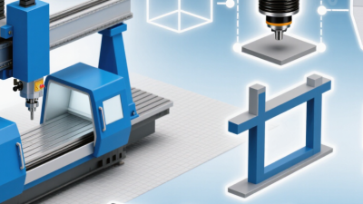
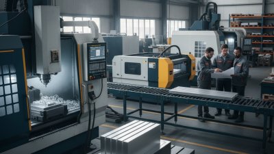
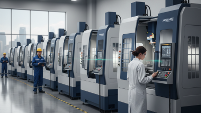
Why Choose a Gantry Machining Center for Global Production?
Global production depends on more than machine speed. Manufacturers must hold accuracy across large components, control setup time, and keep production moving when orders shift between plants. A Gantry Machining Center can address these demands by supporting heavy workpieces and offering a broad machining envelope. Picture a long steel bed, a bridge spanning the table, and a large casting secured for milling without repeated repositioning. That layout can reduce handling and help maintain consistent datum references across multiple operations.
The benefits are practical, not automatic. A gantry machine may suit aerospace structures, energy components, molds, or other oversized parts, but its value depends on the work mix, tooling, operator skill, and service support. Buyers should examine travel, spindle performance, thermal behavior, automation options, and the time needed for installation. These details affect real output more than a headline specification. Ask how the machine performs during long cutting cycles, and how quickly technicians can diagnose faults at the intended site.
That matters.
For companies serving several regions, repeatable processes and accessible maintenance can be as important as raw capacity. A well-selected machine may help standardize production across facilities, though local training and workholding still require careful planning. No single configuration fits every factory. The useful question is not simply whether a Gantry Machining Center is powerful, but whether its size, precision, and support model match the parts your teams actually make. A little skepticism during selection can prevent an expensive mismatch later.
Gantry Machining Centers: Structure and Operating Principles
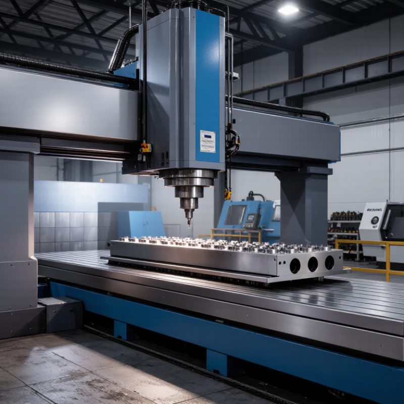
A gantry machining center uses two vertical columns joined by a crossbeam, creating a rigid frame above the work area. The spindle head travels along the beam, while the crossrail may move vertically to suit different workpiece heights. This arrangement can provide access across wide components, such as machine frames or large plates. The table may remain fixed or move along the machine bed, depending on its design. Not every gantry is built the same way.
During machining, controlled movements along the X, Y, and Z axes position the cutting tool against the workpiece. The spindle rotates the tool, and the control system coordinates its path with the feed rate. A rigid structure helps resist cutting forces, but rigidity alone does not guarantee accuracy. Heat, tool wear, setup quality, and machine calibration still matter. For repeated production across locations, documented workholding and inspection routines can help keep results consistent. That takes attention; the structure cannot do it by itself.
Tips:
Check the machine’s working envelope against the actual part, including clamps and tool length. Keep large workpieces supported, and verify alignment before cutting. A missed setup detail can spoil a very expensive part.
Global Production Needs for Large and Complex Parts
Global production often means making the same large component near different assembly plants, not simply shipping one finished part worldwide. A gantry machining center can provide access across broad workpieces, such as welded frames, turbine housings, and long structural plates. For a 2.4-meter component, fewer repositioning steps can reduce alignment errors and setup time. That reach matters.
Large parts rarely arrive perfectly uniform. Castings may have uneven stock, while welded structures can shift during stress relief. A gantry’s work envelope helps accommodate these parts, but capacity alone does not guarantee accuracy. Teams need consistent datum plans, verified fixtures, and probing routines that can be repeated at each site. A small difference in clamping pressure can affect a long surface.
Global teams also need shared process records: tool lists, cutting parameters, inspection points, and revision control. Operators should check spindle condition and thermal behavior, especially when shifts or ambient temperatures change. A practical detail is tool access near deep pockets; the model may look clear, yet the holder can collide. That assumption can be wrong. Local trials and documented measurements help reveal such issues before production scales across facilities.
Why Choose a Gantry Machining Center for Global Production?
Large and complex parts call for generous working envelopes. These illustrative part-envelope examples show how X, Y, and Z dimensions can vary across applications; they are not industry survey data or machine specifications.
A gantry configuration can provide access across a wide work area for machining large structures and complex components. Select machine travel based on the actual part, fixtures, tooling, and required clearance.
How Gantry Design Supports Precision and Flexible Machining
A gantry machining center uses a bridge-like structure to carry the spindle across a large work area. This layout can keep the cutting head supported as it moves over long or wide components. On a fabricated machine frame, for example, operators can reach several mounting faces without repeatedly shifting the part. Fewer setups can reduce alignment errors and save handling time. That matters when dimensions must stay consistent across a production run.
Precision still depends on more than the frame. A rigid bridge helps resist cutting forces, while careful calibration and suitable tool paths help maintain accuracy. Thermal changes can affect large machines, so warm-up routines and measurement checks remain important. Flexible travel also lets one machine handle different part sizes and operations, from drilling patterns to contour milling. Still, details matter. Fixturing, tool condition, and operator experience can all change the result. A gantry design is not a shortcut around process planning; it is a practical way to combine reach, access, and controlled movement. Even a well-built machine may need extra setup time for an awkward component.
Comparing Productivity, Automation, and Operating Costs
For global production, a gantry machining center can improve productivity when parts are large, heavy, or awkward to reposition. Its bridge-style structure supports machining across a broad work envelope, reducing transfers between machines. A casting or aerospace component may stay clamped while several faces are cut. Fewer setups can mean fewer alignment checks and less handling time. That matters.
Automation adds value when production repeats. Pallet changers, probing, and tool management can reduce pauses between jobs, while machine monitoring helps operators spot tool wear or cycle interruptions. Yet automation is not a shortcut around process planning. Fixtures must be repeatable, programs verified, and operators trained to recover safely from faults. Otherwise, a sophisticated cell may wait on one poorly prepared job. Less idle time.
Operating costs need a wider view than purchase price. A larger machine can require more floor space, power, foundation work, and maintenance capacity. Against that, fewer setups, reduced part movement, and longer unattended runs may lower labor and handling costs per component. The balance depends on utilization, part mix, and local service availability. A gantry center is not automatically economical; low-volume work with frequent changes may expose its setup burden. The numbers can be messy.
Selecting and Deploying a Gantry Center Across Global Facilities
Why Choose a Gantry Machining Center for Global Production?
Selecting and deploying a gantry machining center requires more than comparing specifications. Global facilities may differ in floor strength, power quality, humidity, and operator experience. A practical selection begins with shared production data. Review workpiece dimensions, tolerances, tooling, cycle times, and future capacity. Then confirm each site can support installation, calibration, and safe daily operation. Large travel ranges can reduce repositioning, especially for heavy components. However, they also demand stronger foundations and careful logistics planning.
Tips: Create one technical checklist for every facility. Include spindle performance, axis travel, table loading, coolant control, training, spare parts, and response procedures. Request sample machining trials using representative materials. Measure surface finish and dimensional stability. Do not rely only on demonstrations.
Deployment should follow a controlled local plan. Verify the foundation before shipment. Map the machine’s route from unloading point to production area. Prepare digital work instructions with clear photographs and approved settings. Train operators, maintenance staff, and quality personnel together. This reduces handover gaps. In practice, some assumptions fail. A site may have enough space but poor access for maintenance. Another may meet power requirements yet lack experienced setup technicians. These issues should be recorded, reviewed, and corrected before production release. Standardization matters, but flexibility matters too. A single global template rarely fits perfectly.